
| Post-installation hermetic sealing of oil transformers with the Breathing Buffer Box G3B 1.Starting point |
||
| Apart from water, also oxygen is known as an aging accelerator which must be kept away from thermally or electrically stressed oil/cellulose insulations. | ||
| The influence of oxygen on the aging of the oil can be suppressed through inhibitors. The acceleration of the degradation of cellulose begins with advanced thermal degradation and is thus dependent on the stress at an increased age. Therefore post-installation hermetic sealing for transformers of the open type can also have the effect of preserving the substance in later operating years. Post-installation hermetic sealing is also of interest where hermetic sealing that is no longer tight needs to be replaced or secured. | ||
| At newly built transformers, hermetic sealing techniques have been known for a long time, such as N2 cushion, airbag and stretching radiator. However techniques of post-installation hermetic sealing are current innovative solutions, such as Trafoseal and OxyBan. These solutions substitute the short connection from the top of the vessel with a longer one from the bottom of the vessel to the conservator. This is the basis for a diffusion barrier, which stops the continued supply of oxygen from the atmosphere. As a result, vessel oils with an oxygen deficit can show oxygen reduction up to complete disappearance. | ||
| Trafoseal and OxyBan can be cheap alternatives to retrofitting airbags. Such a reconstruction requires the shutdown of the transformer and changes to the safety-relevant concept of the Buchholz relay position. | ||
2.The principle of the Breathing Buffer Box |
||
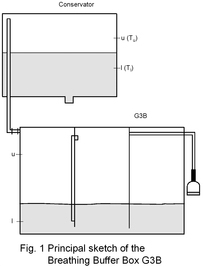 In connection with the transformer with an N2 cushion, also transformers of the open type with a conservator can be changed into this operation mode. Fig. 1 shows the principle of the Breathing Buffer Box (G3B of GATRON GmbH) for this purpose. This is integrated in the breathing line between the conservator and moisture adsorber in such a way that an outer cylinder with the conservator and a bottomless inner cylinder with the moisture adsorber are connected. The box is partly filled with oil. A vertically fixed pipe on the mantle of the inner cylinder which extends into the inner cylinder at the top and is shorter than the mantle at the bottom takes over the gas transport when the upper (u) or lower (l) end position of the inner oil level is reached. Changes in the oil level in the conservator due to changes of the vessel oil temperature cause a modification of the pressure in the connected gas room conservator/outer cylinder (inner air), which leads to a shift of the oil levels in the inner and outer cylinders between the end positions. The design of the G3B is such that one unit can accommodate the thermally-caused volume change of 5 m3 oil for a temperature difference (Tu - Tl) of 30 °C. Dependent on the oil volume of the transformer, this can be done by connecting several G3Bs in parallel.
The oil filling of G3B provides the storage volume for minimal changes in pressure (up to 50 mbar) and serves at the same time as a diffusion barrier for gases, particularly oxygen, as well as for moisture. The latter may be additionally supported by floats in the inner cylinder. In connection with the transformer with an N2 cushion, also transformers of the open type with a conservator can be changed into this operation mode. Fig. 1 shows the principle of the Breathing Buffer Box (G3B of GATRON GmbH) for this purpose. This is integrated in the breathing line between the conservator and moisture adsorber in such a way that an outer cylinder with the conservator and a bottomless inner cylinder with the moisture adsorber are connected. The box is partly filled with oil. A vertically fixed pipe on the mantle of the inner cylinder which extends into the inner cylinder at the top and is shorter than the mantle at the bottom takes over the gas transport when the upper (u) or lower (l) end position of the inner oil level is reached. Changes in the oil level in the conservator due to changes of the vessel oil temperature cause a modification of the pressure in the connected gas room conservator/outer cylinder (inner air), which leads to a shift of the oil levels in the inner and outer cylinders between the end positions. The design of the G3B is such that one unit can accommodate the thermally-caused volume change of 5 m3 oil for a temperature difference (Tu - Tl) of 30 °C. Dependent on the oil volume of the transformer, this can be done by connecting several G3Bs in parallel.
The oil filling of G3B provides the storage volume for minimal changes in pressure (up to 50 mbar) and serves at the same time as a diffusion barrier for gases, particularly oxygen, as well as for moisture. The latter may be additionally supported by floats in the inner cylinder.Dependent on the oxygen deficit, the G3B installation on transformers of the open type in the state of air saturation leads to a decrease in the O2 concentration in the vessel oil. This also includes the inner air which has expanded contact with the conservator oil exchanging with the vessel oil through convection. So, in turn, the O2 deficit in the vessel oil has an effect on the inner air. Hermetic sealing is reached when the O2 concentration is <2000 ppm and the inner air practically consists of nitrogen. |
||
3.Practical application |
||
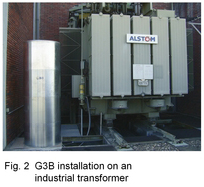 Because of little available space, a system of 4 x G3B equipment was installed on a transformer as a column (Fig. 2) for a target volume of 18.7 m3 of oil. The total weight of about 800 kg required a reinforced ground grid. Moreover, insulation was necessary for protection against weather influences. All this is possible without shutting down the transformer.
|
||
Fig. 3 shows the operating diagram of the TGM monitoring since the G3B installation on 18.09.2008. After degassing, the transformer was considered to be in the resaturation phase till the middle of January 2009 (N2 ≈ 70,000 ppm) with a typical O2 deficit of nearly 18,000 ppm. This phase is characterised by the fact that the oil level in the inner cylinder of the G3B reaches the lower end position as the vessel oil constantly absorbs air, which generates an underpressure and a supply of outer air. This is almost the same as the operation without G3B. After nitrogen saturation, the vessel oil only absorbs oxygen, which decreases the supply of outer air significantly.
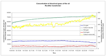 Fig. 3 Resaturation slope with G3B
|
||
The visible O2 decrease in the oil begins now and leads to < 2000 ppm if sufficient operating time is allowed. In the opposite direction, N2 partial pressure increases in the inner air, which leads to increased N2 concentrations in the oil, up to the saturation value for nitrogen at atmospheric pressure. This is where the real hermetic sealing begins. The G3B technique can be coupled with an N2 pressure gas bottle via a level measurement in the inner cylinder. In the lower end position, dry N2 gas can be fed in instead of outer air getting in. This combination allows the number of G3Bs to be minimized at given transformers as well as the hermetic sealing of newly built transformers to be guaranteed from the beginning. |
||