
| Diagnoses according to IEC 60599 |
|||||||||||||||||||||||||||||||||||||||
|
|||||||||||||||||||||||||||||||||||||||
|
Risk factors |
|||||||||||||||||||||||||||||||||||||||
|
|||||||||||||||||||||||||||||||||||||||
|
Risk of false diagnoses according to IEC 60599 |
|||||||||||||||||||||||||||||||||||||||
|
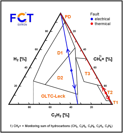
Quality assured gas analyses for transformer diagnostics are necessary
to include all gases in the diagnostics. Only in this way can its complete
efficiency be ensured. In practice there is a risk of false diagnoses through the big differences
in the solubility of the fault gases. The little soluble fault gases H2,
CO and to a lesser extent CH4
are of special importance. An electrical and a thermal fault are
used in order to illustrate the risks inherent in false diagnoses. The FGT shown herein was developed on the basis of the DGA interpretation table of IEC 60599 (the C3 hydrocarbons have been taken into account additionally)[1]. The blue/red dot in the FGT represents the precise and real-time gas emission rate quotients of the dissolved gases in a closed transformer exhibiting a suspect condition. |
|||||||||||||||||||||||||||||||||||||||
|
1. Non-hermetical sampling [2]
|
|||||||||||||||||||||||||||||||||||||||
|
CIGRE TF 15, in its recommendations for how to rule out false diagnoses resulting
from analysis errors during non-hermetical sampling, suggests to forego the testing
for hydrogen (and to consequently also forego the testing for O2,
N2, CO) (Duval triangle). However, an alternative criterion for hermetical conditions (NIS) has been developed. This is met by both the TGM and the EGS method.
Otherwise there is a risk of failure points migrating down.
|
|||||||||||||||||||||||||||||||||||||||
|
2. Openness [3]
|
|||||||||||||||||||||||||||||||||||||||
|
Practical experience has shown that hydrogen (as well as CO and to a lesser
extent CH4) escapes from open transformers.
It is also possible to quantify openness by way of TON determination.
Based on this quantification, correction procedures have been developed for the
purpose of determining the H2 and CO emission
rates while CH4 is contained through summation in CH4
is contained through summation in CH4+.
Otherwise there is a risk of the failure points migrating down (or of the
CO2 / CO ratio rising). Additionally, it is
possible to determine the solution pressure and the oxygen consumption rate.
Moreover, the blue and red dots in FGT also serve to represent the original composition of a Buchholz gas. |
|||||||||||||||||||||||||||||||||||||||
|
3. Oil way / standing time [4]
|
|||||||||||||||||||||||||||||||||||||||
|
Continuous oil contact leads to a gas exchange which in turn leads to the
accumulation of hydrogen (and/or also of CO and to a lesser extent of
CH4). Safekeeping in the TGM and/or in the
AGT (diagnostic accessories)1) as an adjunct to the Buchholz relay allows the
separation of oil way / standing-time and hence paves the way for applying a
correction procedure for the oil way. Otherwise there is a risk of the failure
points migrating up.
[1] EW Jg. 108 (2009) Heft 17-18, S. 70-75 [2] EW Jg. 111 (2012) H.14, S. 50-55 [3] EW Jg. 109 (2010) H.14-15, S. 56-59 [4] EW Jg. 98 (1999) H. 25, S. 16-24 |
|||||||||||||||||||||||||||||||||||||||
| 1) Product announcement EMB GmbH | |||||||||||||||||||||||||||||||||||||||