| Determination of the fault type from Buchholz gas analyses |
| 1.Practice of the Buchholz gas |
| IEC 60599 describes the Buchholz gas in detail. The conditions of formation and the gas exchange determine the composition of the Buchholz gases. While the fault type and spontaneity are of decisive importance for the formation, the gas exchange is dependent on the way the bubbles take through the oil and the degree of gas saturation. As the free original gas is not accessible for direct analysis on the fault location, the well-known quotient criterion is used for the diagnosis of dissolved gases. The composition of the original fault gas is identical to its composition when completely dissolved in the oil. Despite the gas exchange, each Buchholz gas actually provides information direct from the fault location as long as the equilibrium state of the oil is still far way enough from being reached. According to the standard, this is checked with the help of the equilibrium criterion by calculating the concentrations in the oil from the Buchholz gas analysis using solubility coefficients and by comparing with a simultaneous gas-in-oil analysis (DGA). This is hard to achieve in practice because organisational and technical measures prior to sampling often take several hours. The standard states that the Buchholz gases need to be sampled immediately after signalisation. Consequently, there is a risk that gases which dissolve well are lost for analysis. The calculation of fault gas quotients which the standard uses to determine the fault type is based on the oil concentrations of the fault gases derived from the Buchholz gas, which applies in equilibrium state. This means that the direct information from the Buchholz gas on the fault location remains unused. |
2.Use of the diagnostic potential |
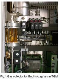
 The diagnostic potential of the Buchholz gas cannot be used completely unless the time after sampling is short and a correction to the original composition on the fault location is made. The techniques for the sampling of Buchholz gases which IEC 60567 describes have no influence on the time that elapses between sampling and signalisation. This can partly be achieved using the gas extraction device
 |
| In order to consider the actual gas exchange of the Buchholz gases with the vessel oil for a correction, a model of bubble rising in air-containing oil been
developed. The model is based on the fact that the air is desorbed from the oil in the same way as the fault gases are absorbed by the oil. Extensive model calculations consider the parameters initial bubble size and composition as well as oil quantity, air saturation and temperature. The point of interest is the graphs of the absorption and desorption quotients. The quotient of the fault gases increases logarithmically with the oil quantity whereas the O2 / N2 quotient falls in linear way. This formed the basis for the development of a correction procedure (E. Bräsel et.al.; Neue Hilfsmittel zur Diagnoseeignung von Gasen aus dem Buchholzrelais; Elektrizitätswirtschaft 25/99, S. 16-24). |
3.Practical application |
| In case of a gas alarm, the transfer of Buchholz gas into the gas collector via a potential-free contact is started on the TGM location. Simultaneously, the Buchholz gas is transported direct into the gas space of the equilibrium column. A quick analysis on the basis of an online hydrogen difference measurement compared to the equilibrium gas is made. This yields the result “fault gas or air”. The TGM functionality also includes the daily check of the Buchholz relay in terms of gas collection and automatic hydrogen measuring. In case of Buchholz warning, the total accumulated gas volume is also determined when the automatic de-airing is finally performed. |
| For the determination of the fault type, the BGS is used to take a sample from the gas collector which is then analysed in the laboratory together with an oil sample. The results serve to determine all the fault gases involved in the fault on the basis of the equilibrium criterion and to establish the number of oil contacts from the air quotients in the Buchholz gas and oil. Starting from the Buchholz gas, this number allows the quotients of the original fault gas to be calculated. |
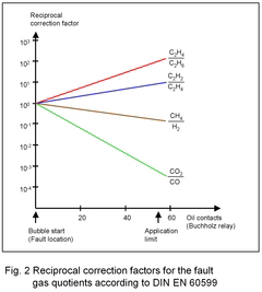
 Fig. 2 shows the changes in the fault gas quotients including the quotients for carbon oxides which are used in IEC 60599. The quotients of all gases are set on bubble start to the standardised value 1. From the number of oil contacts (model parameters) to the Buchholz relay, the quotients change differently, which is due to the differences in
their solubility coefficients. As an example of a correction, a number of 40 oil contacts can be assumed to be representative for a spontaneous gas collection on the Buchholz relay. With the help of the quotient lines, the reciprocal correction factors have to be calculated. The quotients determined in the Buchholz gas are then divided by them to obtain the quotients on the fault location. In the present case, the fault gas quotients of the fault location and the Buchholz relay would differ by up to two times power of 10. The diagnostic limits set do not consider this. Thus it is only the quotients on the fault location (original fault gas) which are suited to determine the fault type according to Table 2 of the standard or to show the fault type with the help of the Fault Gas Triangle (GATRON GmbH).
|